Friday 27 December 2019

Parting Ways...........

     Due to export / import costs, it is not practical for me to take my bike home to the UK. Unless I find a way, I am selling my much loved project before my return to to Scotland.
     This is a sad day, needs must when the devil is driving. If you are interested, drop me a line.


     Will start another project when I find one back home in Scotland.

Friday 27 September 2019

My first build, FZR600R in yellow.

    As I am away at home in the UK at the moment, in between various jobs to be done, I got my loved 600 out for a wash and refresh.
    It's a light tuned FZR600R. The paint job was born, like most of my work from costs and necessity. SAR yellow,  which lead to the choice of Camel Racing Rossi colours. Lots of fun and can't wait till next spring, 2 bikes with different characters to choose from.


Monday 9 September 2019

Seat Unit Modifications before paint......

     Before I get my 'tins' painted, there is a modification I need to do. So as not to spoil the lines of the tail unit. Just so as not to spoil the tail lines, a little like the bike below:


     The thing is, I hate paying too much, a modified rear seat pan is around double that of the one I have, the tail light is an LED item from eBay, costing $6.00 including delivery. The pipe was the same from home depot. A couple of thinking days later, some measuring and more thinking the shopping list was compiled. Fiberglass repair kit, 2" PVC pipe and a 2" PVC pipe connector to make and recess the light. 
     Off to the late I goes, opening one side of the connector to accept the tail light mount and to cut and open out the PVC pipe to accept the lens. The two parts then glues together ready for shaping to fit the tail unit. Once fitted the unit center line will be marked, the pipe shaped to the correct contour and then rough mounted. The initial mounting enabling the positioning and marking of the hole to be cut in the seat unit (I know - very sweaty moment and large cojones required for the cut).


     Progress so far has been made, just the shaping and cutting to go. The some light gluing, fiber-glassing and lots of sanding to get the smooth lines I desire.  Once fitted - it's off to the paint shop!


Saturday 31 August 2019

Finished Footrests!!

     The holiday / Hurricane week end, before any weather arrives to force me to runaway from Florida for a bit - I took the opportunity to finish the 'pegs'.
     Firstly they needed marking up for the 8mm holes for the securing pins. I had to round 2 flats so they slid into the holders correctly, then mark up the centers of the holes. This was done, then each piece mounted into my milling machine, for centering - counter sinking and drilling to 8mm:

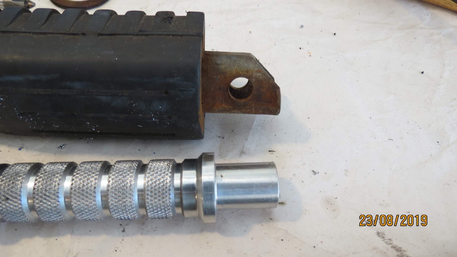
The holes were drilled in 3 stages, counter sink, 4mm and then the final 8mm hole. I ran the mill at the correct speed for the steel insert rather than for aluminium. Seems a sensible course, avoiding excess heat from the steel and  possibility of blunting the drill bit or worse. Once both rests were drilled i re fitted them to the rear-sets, just to ensure a nice fit.
     Chem-bluing the hex part of the rests, I then marked the 45 degree slant, when machined off the angle will allow the rests to pivot up (for when I get the knee down - and no hero blobs to worry about....). The pieces were marked up and then each mounted back in the milling machine,  my cutter of choice being a 4 flute 3/4" end mill. The mounting complete i cut the angles to half the across the points depth, basically to the center of the rest. The cutter was a hot knife through butter.


Once both pieces were cut they were cleaned. Not sure if I am going to polish them as yet as I like the contrast in finish and form. The the securing pins were given a good clean and parkerized. Giving them a black to grey look. The all pieces were cleaned one final time, checked for fit and assembled.


     I am very pleased with the final finish. The pegs from Barry were nice, and I was determined to put them on my bike. That is now possible, with a little bit of thought and engineering know-how. The picture below shows the rear-sets, pegs and securing nuts. All bespoke pieces finished to within 2 thou and giving a great sense of achievement.


     Now onto the next part of the build, I do keep saying engine, but I am working up to that. I now have the tail light and the seat unit will need modifying to accommodate it. The intention is to recess the light into the unit. Beer-o'clock now.

Saturday 24 August 2019

Footrests - part 2. A third installment will be called for I think.

     Beer was good, I have a penchant for PBR, refreshing and tasty. So a few days later I get to designing and machining the foot rest nuts, for the other side of the rear-sets. You can see them below, My original design did not turn down the outer side of the nuts but the finish was clunky and, dare I say, amateurish, lacking in thought and refinement. S, after a little thought and some math, one prototype later, a finished design was settled upon. Off to the lathe.
     I had some hex aluminum stock, 3/4" across the flats, this was my metal of choice - mainly because it suited my needs, was free and is very easy to machine.

     Firstly, the holes for the frame mounts were drilled, tapped and counter drilled to fit the bike:


     An easy and straight forward task, KAWASAKI do everything in metric, I have an old American Sheldon lathe, acquired 6 years ago from the back of an old army service trailer in a junk yard. Dealer said if I could get it out I could have it (Oxy--acetylene torches, 5 ton army repair trailer suspended under a crane, July in Georgia and a near death experience). Bob's your uncle, I was the - much to my wife's delight - the proud owner of a lathe, albeit at the time in dire need of a lot or work to get it running. Once the holes were done, the overall depth being approx. 7/8", and the M8 X 1.25 mm tapped hole being approx the deeper 1/2" or so. All depths calculated and the drill bits marked with tape for ease of production. The bar was then turned to 5/8", to match the rear set bushed holes:


     Once this was completed, the stock was cut to just over an inch in length. Then turned to the required inch and then turned to 3/4", mostly because that was aesthetically pleasing to my eye. Then the ends had a complimentary angle put on them.


     Repeat four times and hey presto - securing nuts for the rear sets. Now, this is when, on further inspection, the rather nice racing foot pegs that Barry gave me do not fit the hangers. The space being 3/4" and the foot rest ends being 5/8" in diameter. As you can see from the picture below, some more engineering was demanded.

 I measured, re-measured and then got to work. As it turned out, the hex stock I have been using for the securing nuts fits the foot rests. I elected to use that as the starting point. Being all aluminum worried me to the point where it was decided that instead of just boring the aluminium stock out to 5/8", interference fitting the pegs and mounting into the rear-sets. although a nice solution, is inherently weak, being all aluminium. Ah-ha! I will produce a steel liner for the hex stock, interference fit that, then fit foot pegs into the liner, and then into the rear sets. I am a genius! So a steel sleeve was produced, forced into the prepared hex stock, with some metal epoxy - courtesy of Gorilla Glue for extra security. There will also be a cross pin when fitted to the bike, this is where the pegs will pivot.


     I faced off the piece and will let it  cure for 24 hours prior to drilling the cross hole for the fixing pin, machining the 45 degree angle to facilitate the rests moving up and back to horizontal, when i ground the pegs in a corner......


     The foot rest production so far shown above, not to shabby, very bespoke and, as it turns out, cost effective. I have about 2 1/2 hours vested in production and another 2 1/2 in mistakes and fuck-ups. Another hour or so will see them complete and mounted. More to follow in installment 3!

Saturday 17 August 2019

Footrests (part 1) - An ode to Mr Smith (metal-head), Barry (the dad-in-law) and paying attention

     Measure, measure again - have a think, then measure and cut. It is testament to machinists everywhere, the old maxim of measure twice and cut once used to work.....
     The having a think precludes making my mistake on mounting of the rear sets and having to artistically un-fuck a perfectly executed piece made for the wrong hole on an assumption. Mr Smith, my old metalworking teacher was right, always check and recheck your work.
     After a taxing week of a daughter's university graduation, which included being rear-ended by a Hyundai something or other, resulting in having to deal with the Fire, Police, ER and GEICO, my week was definitely yin and yang. My gorgeous and foxy wife having a concussion and a few bruises was on binge TV rest for the week to recuperate. Off to the garage I trots, cell in hand - just in case my skills as a reassuring and fine husband were needed to fulfil my baby's needs.

     The rubber bushes I needed to replace were knackered. Two had disintegrated on removal of the rear sets, the other two looked like a T-REX chew toy:


     So I luckily find a piece of polymer (no - NOT her rolling pin), a silent yelp of joy and a quick measure resulted in a perfect piece to mount the foot rests to the rear sets. At this point I should state the piece I was trying to make was the bushings to mount the rear sets to the frame....DOH! I could hear Mr Smith chuckling in my head and asking how I was going to rescue the only piece of polymer i had for the task it was intended. HaHa! After a night of thought and beer the ghost of engineering past paid me a visit. What I had made is bushing for the aluminum bushing for the rear sets. All I needed to make as the aluminium pieces. So I measured, thunk a bit, re measured and then produced my inside bushes:


     As you can see, the improved 2 piece bushes replace the Kawasaki originals, should be harder wearing and isolate any vibration still from the engine, and giving better feed back from the bike when riding. Everything is an interference fit (everything had 2 thou of an inch oversize), a little percussion help in the fitting of the bushings, they went in well.

     The completed pieces - seen to the left - look so good when in place. These hangers will house the very nice aluminum RGV race pegs Barry gave me on my last visit home to Scotland.
     All in all, a good way to un-fuck a stupid moment and actually improve on my original idea, and machine some easy pieces.
     Yes I know a lathe is essential, I have one, so I can produce a lot of stuff and save a lot of money to boot. I heartily recommend the acquiring of such an item. eBay, craigslist and FB Market place has a wide choice at reasonable prices.
     The old heavy rubber foot rests will be gone, a saving of about a pound in weight as well as the new shiny pieces looking a whole lot better:


     An old rest is to the top right of the picture for reference. The shiny aluminium piece will be fitted soon. Now all I need to do is make the external bushes to finish the mounts. They will probably include a thread to the external bush is also the securing nut to fix the rear sets to the frame. Oh and make a sleeve for the ends of the rests so they fit into the rear sets. But enough for  today. Beer-o-clock.

Tuesday 9 July 2019

The Carbs.......and i don't mean potatoes!

     The day has come, it's carb time.
In need of a good service........and a clean


     I took a deep breath, exhaled and repeated, carbs are a black art. That's what I thought, thta's what I feared. "Oh well - in for a penny, in for a pound". I prepped my work area and got the tools for the job, various flat head and cress head screw drivers, carb clean, WD-40 and a plethora of shop wipes.
    I tentatively took the carb top covers of, then sighed, realizing I needed a carb kit and gaskets....off to eBay I trotted. The card servicing kit, and the subsequent correct lower gaskets rushed me a michty $45.00:
 

     The float bowl gasket for my KZ650C are slightly different to the ones supplied in the kit, can you see the difference above? Anyways, the prompt arrival of my parts facilitated my carburetor adventure.
     Back to the work bench I went, and started. Now I am usually methodical to start and then as the confidence grows, neat and tidy goes. This was not going to happen this time. After reading much about jets and exhausts, being none the wiser it was decided to go with 102.5 main jets as the bike is going to get a nice 4 into 1 set of pipes.
     Tops off and bits out (fnar fnar, hehehe). These have not seen the light of day since they were built, or so I suspect. The insides were covered in a powdery residue and stains. The logical approach to cleaning and servicing began:

The carbs were testing me, but I was triumphant. I managed to get them off the mounts, separated and apart. Initially laying them out in order on the bench, so as to assemble beck in the same order. Clever eh? The the cleaning, mainly with alternating WD-40 and carb cleaner. I decided to give the card covers a bit of a polish, but not to much. Not wanting a mirror finish on them. Wanted them more 'enginey'. As you can see from pictures, they buffed up and cleaned out none to shabbily.  The throttle bodies and needles
were carefully disassembled and cleaned, needled and washers replaced and put back together. The float assembly was given the same treatment, as were the floats and float bowl. The jets were removed, being replaced with the afore mentioned 102.5 pieces.
     The exterior of each carb was gently cleaned, again, no painting or rough treatment. Then the piece was assembled and put to one side.
Dry and dusty
     Rinse, repeat four times. The carbs them selves are now clean. The next challenge was the choke, mount and fitting my newly acquired pod style air filters. Another eBay acquisition, and, as with all eBay transactions, 3 weeks later a set of K&N pods sold for the same price as my 'replicas'.
     First of, all connecting tubes and bodies were thoroughly cleaned, my attentions now going to the aluminium mounting bracket. I did think on polishing the whole thing. Decided that i did not have the time of patience for than, so it was cleaned and sprayed the same gunmetal shade as other parts of the KZ. High temperature paint being the weapon of choice. Then final assembly began, so far so good and all very methodical. When i got to the installation of the choke, it was decided that the mounts and choke pieces were to be cleaned and parkerized. Good job i used to do this a lot for my guns.Do a quick go on the wire brushes and into the 'goop' for ten minutes. Whils the pieced were cooking I cleaned and painted the choke lever. All looking fine now.
     The putting together of the puzzle was easier than i expected and results pant wettingly satisfying. The pictures do the work som justice, but, mmmmm.


     My, what great pods. Well actually if they perform as good as they look, my KZ caferacer will sound and perform most satisfyingly. Here are a few more pictures, just to complete the story:
 You can see the colour used for the bracket in this picture. 2 primer coats and 3 wheel paint coats. The overall outcome was very nice indeed. All screws were lightly polished and the same for the bolts. Again, I stress that i do not want to over restore the bike at this stage, just get it to a very nice and rid-able condition, and then iron out it's foibles and change what I need to, so the bike lives and evolves.


     That was that, they took a week or so in all, what with work and the long haired colonel needing my attention too. I am satisfied with the results, I just hope that not too much tweeking will be needed. I may employ the help of an engine guru, now to find one here in Jacksonville. And now the last big piece for the build. The 650 lump..........


Monday 10 June 2019

Some good bits from the father-in-law

    Here I am, visiting the UK, a sabaticle if you will. Barry, my father-in-law,  a body work guru and former race team owner, all round nice guy gave me some bike bits. He is an RGV specialist and back in the day - when caferacers were not retro, quite the racer and he hung in all the right circles with some world class riders.
    Any how, he gave me some aluminium foot pegs, brake peddle and gear lever. Saving me time and getting more of those pieces on the bike. The lever will get painted black, over the blue anodizing.


     Oh, and a couple of in line fuel filters too. All most welcome and will make it to my build.  There will be a little fabrication and bespome building to fit them. Happy days, thank you Barry.

Monday 29 April 2019

A trimmed and polished front fender.

     This one bit me, more on that later. The 70's chrome fender is definitely period, and not entirely in the cafe-racer style it had to be fixed. Again, in the spirit of my build, modification of the existing part is more desirable than a purchase of a fiber-glass replacement. The fender was showing age related spotting on the chrome to just outright rust.


     First, as can be seen, i measured the fender, electing for something trimmed at both ends and half its current length. The initial cut lines can be seen on the picture above. Cutting something that you cannot undo is quite daunting at first, so i started with a straight trim along the lines and then slowly cut into the line i traced from the original front piece. The rear of the fencer has a den in it, so had to do anyways.

     With my trusty 4.5" grinder, i cut away and shaped. For smoothing out the curves, finding a pivot point for the fender and keeping the grinding wheel stationary and pivoting the fender produced so very satisfying results. You can see from the pictures. I have found that my 4.5" grinder has been invaluable. So, after shaping i ground out the rust, using the wire wheel attachment. It bit me. I t was my fault, trying to hold both the grinder and fender. The grinder skipped and dragged itself across my stomach, producing a rather nice road rash and and ouchy. Something you only do once! Lesson learnt. After checking I had not been disemboweled, the underside of the fender edges were filled with metal filler, removing the sharp edges and masked off for painting. 2 coats of primer and 2 of the gun metal wheel paint. The fender looks good:


     The tape removed and a final polish was done. I may try some type of chrome restoration on the fender, but for now, job done:


     Front end is now almost complete. Pictures and a video will follow.


Wednesday 24 April 2019

The Headlight.........

     OK,  I hear you, where has he been? Why no updates for a while. The simple answer work and more work making demands, can't wait to retire. Anyhow, back to the blog and my bike. Every day I do a little bit, if I can, the familiar words to the missus "Babe, just popping in the garage for 10 minutes...". Oh, how she knows me, her reply "See you in 3 hours then!".
     The main focus of my attention this week has been the 'Bubba'd' head light. Yes - I could have purchased a new on, but that goes against what I am trying to achieve here. After a little searching in my garage, and the thought "I know it's here somewhere.", I found the remains of a fiberglass kit, with just enough of everything I need to refurb the head light. The surrounds have been powder coated by the very talented people at Powdertechplus of Orange Park, and the cover is going to be my task.


     As you can see, the hole in the back looks like it was cut with a 1930's tin opener. I set about sanding and then fiberglass over the hole and getting an enclosed cover to start with. Sanding with 220 grit and then 500 grit paper, to get it smooth and a good key for the fiberglass. I then formed the inside of the cover.


     Having let the inside cure, I then formed the outer surface. As it turns out, it hasn't come out too badly, especially with my skill levels as a body work guru are average. The next stage came out thus:
  

     And then to the out side, more sanding and priming. I did get a blister on my thumb (Dire Straights), sanding. More gloves needed. As I have found, most skills are learn-able, even if only at a basic level, but, I think, in this case it has been worthwhile, if only costing me time. It has saved the cost of a new headlight.
     I then primed and sanded and primed the light housing to achieve a finish i was happy with, or as near as i could get to it. Perfection is a question of time, skill level and patience. I have some of these and perseverance. Once primed i elected to put my first coat of Gloss Black paint on, then, more after I realized than by design, cut the hole for the wiring in the cover. This i completed with a 2 inch hole drill, the kind that is a circular saw with a drill bit in it. Thus completing the initial fit. The hole was cut in pretty much the same place as the original 'Bubba Cut', and is so much cleaner and pleasing to the eye.
     You can see how the hole cutter worked from the picture to the right. There was a little fraying of the glass inside the cover, but that sanded out with no issues.  The rattle can finish is not as good as a professional job, but is so much improved over what was on the bike, and I have again salvaged a case for the dumpster into a very usable piece. It does, at this stage need a light 2000 grit wet and dry followed up with a gloss lacquer to finally finish it. That will be tomorrows job, once the paint has cured.
     Paint cured, sanded and touched up. Lacquer applied, sanded and repeat. The cover is done. As a rattle can product, i am quite pleased with the overall result. Yes, it could be improved, but I am using my time as well as I can, learning and applying new skills as a task presents itself. Once my bike has been completed to it's initial stat, it becomes the embryonic state and will evolve. So cover completed, have looked for, and ordered the indicators, eBay specials. Will publish more on the completed front end soon For now, here is the finished cover picture, will assemble the headlight once indicators have arrived.