I had some hex aluminum stock, 3/4" across the flats, this was my metal of choice - mainly because it suited my needs, was free and is very easy to machine.
Firstly, the holes for the frame mounts were drilled, tapped and counter drilled to fit the bike:


An easy and straight forward task, KAWASAKI do everything in metric, I have an old American Sheldon lathe, acquired 6 years ago from the back of an old army service trailer in a junk yard. Dealer said if I could get it out I could have it (Oxy--acetylene torches, 5 ton army repair trailer suspended under a crane, July in Georgia and a near death experience). Bob's your uncle, I was the - much to my wife's delight - the proud owner of a lathe, albeit at the time in dire need of a lot or work to get it running. Once the holes were done, the overall depth being approx. 7/8", and the M8 X 1.25 mm tapped hole being approx the deeper 1/2" or so. All depths calculated and the drill bits marked with tape for ease of production. The bar was then turned to 5/8", to match the rear set bushed holes:

Once this was completed, the stock was cut to just over an inch in length. Then turned to the required inch and then turned to 3/4", mostly because that was aesthetically pleasing to my eye. Then the ends had a complimentary angle put on them.

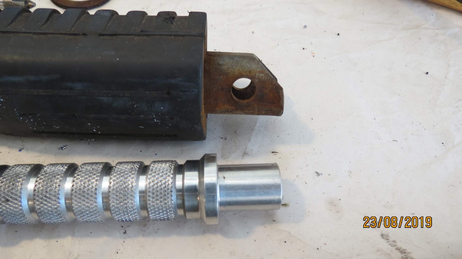
Repeat four times and hey presto - securing nuts for the rear sets. Now, this is when, on further inspection, the rather nice racing foot pegs that Barry gave me do not fit the hangers. The space being 3/4" and the foot rest ends being 5/8" in diameter. As you can see from the picture below, some more engineering was demanded.

The foot rest production so far shown above, not to shabby, very bespoke and, as it turns out, cost effective. I have about 2 1/2 hours vested in production and another 2 1/2 in mistakes and fuck-ups. Another hour or so will see them complete and mounted. More to follow in installment 3!
No comments:
Post a Comment